GRACE TECHNICAL REPORTS
Towards Compositional Approach to Model
Transformation for Software Development
S. Hidaka
Z. Hu
H. Kato
K. Nakano
GRACE-TR-2008–01
August 2008
CENTER FOR GLOBAL RESEARCH IN
Towards Compositional Approach to
Model Transformation for Software Development
Soichiro Hidaka†
Zhenjiang Hu†
Hiroyuki Kato†
Keisuke Nakano‡
†National Institute of Informatics
{
hidaka,hu,kato
}
@nii.ac.jp
‡The University of Electro-Communications
[email protected]
August 2008
Abstract
Model transformation plays an important role in Model-Driven Soft-ware Development that aims to introduce significant efficiencies and rigor to the theory and practice of software development. Although models may have different notation and representation, they are basically graphs, and model transformations are thus nothing but graph transformations. Despite a large amount of theoretical work and a lot of experience with research prototype on graph-based model transformations, it remains as an open issue how to compose model transformations. In this paper, we report our first attempt at a compositional framework for graph-based model transformations based on the graph query language UnQL. We show that the idea of UnQL that graph queries are fully captured by structural recursion can be adapted to structure graph transformations to attain efficient composition of model transformations. We have imple-mented a prototype of the framework and tested with several nontrivial examples. Our new framework supports systematic development of model transformation in the large, while guaranteeing that inefficiency due to this composition is automatically removed.
1
Introduction
Model-driven software development [11] is an emerging technology that aims to introduce significant efficiencies and rigor to the theory and practice of software development. MDSD advocates models as the key artifacts in all phases of de-velopment, from system specification and analysis, to design and testing. The use of models and the application of model transformations open up new possi-bilities for creating, analyzing, and manipulating systems through various types of tools and languages; each model addresses one concern, and the transforma-tions between models provide a chain that enables the automated development of a system from its corresponding models.
notation and representation, they are basically graphs, and model transforma-tions are thus nothing but graph transformatransforma-tions. This has led to the so-called graph-based approach [10, 14] to model transformations based on heavily the-oretical work in graph transformations [1, 7, 21]. The graph-based approach is powerful with a large amount of theoretical work and a lot of experience with research prototypes. However, it remains as a challenge to use it to develop model transformation in the large, which requires a composition mechanism with high modularity [8]. In a recent survey paper [10], it says:
Open issues for all graph transformation approaches are elaborated concepts to compose transformations ...
Put it more concretely, the problems are:
• First, although the graph-based approach is declarative in the sense that a transformation is specified by a set of graph rewriting rules, there lacks a good support for composing model transformations so that a set of new graph rewriting rules can be efficiently derived from those of two transformations that are composed.
• Second, the graph-based approach is very complex, which stems from the
non-determinism in scheduling and application strategy of transformation rules, which requires careful consideration of termination of the transfor-mation process and the rule application ordering (including the property of confluence). In most systems based on graph transformations, a graph rewriting rule is not executable unless it is accompanied with a complex rewriting engine.
From the practical point of view, model composition would be necessary if one wants to chain and combine model transformations to produce new and more powerful transformations. To bridge large abstraction gaps between two models, it is often much easier to generate intermediate models rather than go straight to the target model. This would make model transformation more modular and maintainable.
In this paper, we report our first attempt at a compositional framework for graph-based model transformations, which cannot only support concise spec-ification of model transformation, but also simplify and improve efficiency of model transformation implementation and execution. This work was greatly inspired by the compositional graph querying language UnQL [5], which has been intensively studied in the database community. The key idea of UnQL is that graph queries are fully captured by structural recursion that are suitable for efficient composition. We show that this idea can be adapted to structure graph transformations to gain efficient composition too. Our main contributions are two folds.
First, we propose a compositional framework for graph-based model trans-formations based on the graph querying language UnQL. We have made three important extensions over UnQL.
• We add the graph schemes to UnQL and give an efficient validation
• We extend UnQL with three simple graph editing constructs so that model transformation can be directly and convenient described.
• We show that all model transformations in the extended UnQL, called
UnQL+, can be mapped to structural recursions that are suitable for
ef-ficient composition.
Second, we have implemented a prototype of the new framework and tested with several nontrivial examples. Our new framework cannot only support systematic development of model transformation in the large, but also guarantee that inefficiency due to this composition can be automatically removed.
• We demonstrate, with the nontrivial model transformation from classes
to relational database management system, that a large model mation can be systematically developed by gluing simpler model transfor-mations.
• We show that by representing model transformations internally by
struc-tural recursions or their composition, we can automatically eliminate in-efficiency due to the introduction of composition by fusion optimization. The experimental results show promising speedups by fusion optimization.
The organization of this paper is as follows. We start by considering a typical but nontrivial model transformation, called Class2RDBMS, which will be served as our running example, in Section 2. Then we show how UnQL and its extension can be useful for systematic development of model transformations in a compositional style in Section 3, and we explain the architecture of our compositional framework and its detailed implementation in Section 4. We discussed the related work in Section 5, and conclude the paper in Section 6.
2
An Example: Class2RDBMS
As a running example, we consider the model transformation, Class2RDBMS, a simplified version of the well known ”class to RDBMS” transformation. It was proposed as a common example to all the participants of the International Workshop on Model Transformations in Practice 2005 [3], whose purpose was to compare and contrast various kinds of approaches to model transformations. We shall explain the requirement of this model transformation in this section, and leave the details of how this model transformation can be described in our framework in Section 3.3.
2.1
Class Models
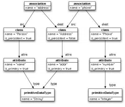
Figure 1: A Class Model
Figure 2: A RDBMS Model
2.2
RDBMS Models
An RDBMS model consists of one or more tables. A table consists of one or more columns. One or more of these columns will be included in the pkey slot of a table, denoting that the column forms part of the tables primary key slot. A table may also contain zero or more foreign keys. Each foreign key refers to the particular table it identifies, and denotes one or more columns in the table as being part of the foreign key. Figure 2 shows a RDBMS model that has two tables.
2.3
Transforming Class Models to RDBMS Models
column is established. If the type of an attribute or association is another persistent class, a foreign key to the corresponding table is established.
If class hierarchies are transformed, only the topmost classes are mapped to tables. Additional attributes and associations of subclasses result in additional columns of the top-most classes.
Non-persistent classes are not mapped to tables, however, one of the main requirements for the transformation considered is to preserve all the information in the class diagram. That means attributes and associations of non-persistent classes are distributed over those tables stemming from persistent classes which access non-persistent classes.
This model transformation is not so trivial. We will show in Section 3.3 how to systematically develop it in our compositional framework.
3
Model Transformations in UnQL
+In this section, we shall explain the language UnQL+, a small extension of the
graph query language UnQL [5], and show how it can used to describe model transformation in a compositional manner. First, we review the basic concepts
on UnQL and its core UnCAL. Then, we extend UnQL to UnQL+ with three
editing operations. Finally, we demonstrate how to systematic develop model transformations with the example of Class2RDBMS.
3.1
UnQL: A Graph Querying Language
Our compositional framework for model transformations is based on UnQL [5], a language that was originally designed for querying unstructured data such as graphs. It has convenient select-where style surface syntax, which are translated into core graph algebra called UnCAL that consists of a small number of basic constructors and operators. Its expressive power is FO(TC) (first order with transitive closure), and complexity in answering UnQL query is PTIME. In this section, we briefly review the basic concepts of UnQL, which will serve as the basis of our framework.
3.1.1 Graph Representation
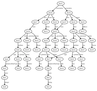
In UnQL, graphs are edged-labelled in the sense that all information is stored as labels on edges rather than on nodes (the labels on nodes have no particular meaning). It can be directly used to represent model. For example, Figure 3 shows a graph that represents the model in Figure 1. Formal definition of this graph representation will be given in Section 3.1.4.
3.1.2 UnQL
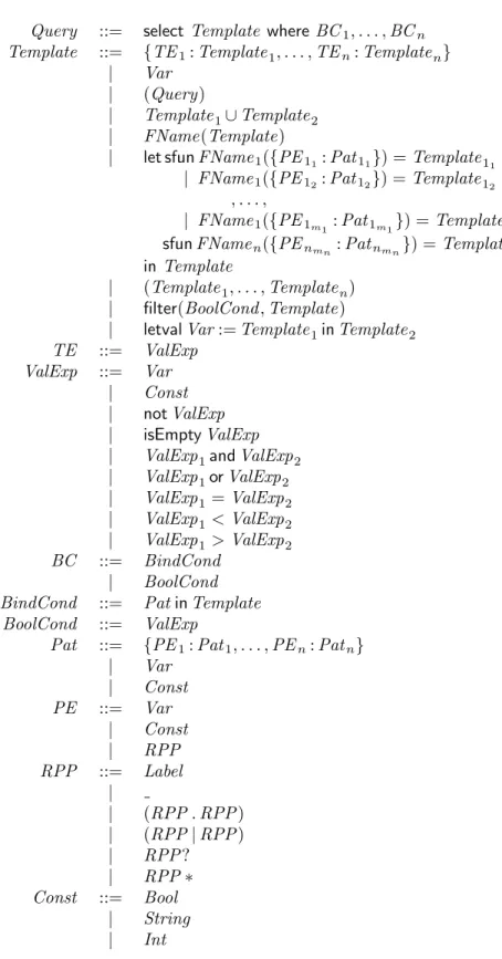
UnQL, like other query languages, has a convenient select-where structure for extracting information from a graph. We omit the formal definition of the language syntax, which can be found in Figure 13 in the Appendix. Rather we give some examples.
Bid1 Bid0 Integer Bid2 name Bid4 Bid3 String Bid5 name Bid6 primitiveDataType Bid7 primitiveDataType Bid8 type Bid10 is_primary Bid12 name Bid9 true Bid11 number Bid13 type Bid15 is_primary Bid17 name Bid14 true Bid16 addr Bid18 type Bid20 is_primary Bid22 name Bid19 true Bid21 name Bid23 attribute Bid24 attribute Bid25 attribute Bid26 attrs Bid40 is_persistent Bid42 name Bid39 true Bid41 Phone Bid27 class Bid28 dest Bid32 name Bid30 src Bid31 phone Bid29 class attrs Bid44 is_persistent Bid46 name Bid43 false Bid45 Address Bid33 class Bid34 dest Bid38 name Bid36 src Bid37 address Bid35 class attrs Bid48 is_persistent Bid50 name Bid47 true Bid49 Person Bid51 association association
Figure 3: A Class Model Represented by an Edge-Labelled Graph
(* Q1 *) select T where
{association:{dest: {class:{attrs:
{attribute:{type:
{primitiveDataType.name:T}}}}}}} in db
If we use the regular path pattern, all primitive data types that occur any-where in the hierarchy can be easily obtained by the following queryQ2:
(* Q2 *) select T where
{_*.primitiveDataType.name:T} in db
More involved examples can be found in Section 3.3.
3.1.3 Structural Recursion in UnQL
Structural recursion plays a very important role in UnQL. Not only can it be used to described many useful queries, but also any queries in UnQL can be described in terms of structural recursion.
Structural recursive functionf in UnQL is a simple mutually recursive com-putation scheme, satisfying the following two equations and guarantee that no return value of any function should be fed to another function.
f {} = {}
This simplicity allows manipulability of structural recursion which is a combina-tor that is similar to the higher-order function map in functional programming languages. Whereas map is applied recursively to tails, structural recursion is applied (vertically) to nodes, as well as (horizontally) to edges.
As a simple use of structural recursion, the following queryQ3 replaces all
labelsname underprimitiveDataType in Figure 3 withtypeName. Due to the
two equations above, definitions for horizontal recursion are always omitted.
(* Q3 *) select
letrec
sfun f1 ({primitiveDataType:T}) = {primitiveDataType:g1(T)} | f1 ({L:T}) = {L:f1(T)} and sfun g1 ({name:T}) = {typeName:g1(T)}
| g1 ({L:T}) = {L:g1(T)} in f1(db)
3.1.4 Data Model
UnQL data model is based on edge labeled, rooted, directed cyclic graphs, whose orders between outgoing edges of a node are insignificant. Nodes may be marked with input and output marker, both are denoted by &x∈Marker, whereMarker
is an infinite set of symbols. A node marked with input and output marker is called input node and output node, respectively. Input markers are used to select entry point of the graph, whereas output markers are used to glue output nodes with input nodes of a graph.
Formally, a graph g is denoted by a quadruple (V, E, I, O), where V is a subset of (possibly infinite) set of nodes ˆV, a set of edgesE⊆V ×Labelϵ×V
whereLabel stands for infinite set of labels, and we denoteLabel∪{ϵ}byLabelϵ.,
a set of pairs of input marker and associated node I ⊆ X ×V, and a set of
pairs of output nodes and associated output marker O ⊆ V × Y. Each of
these component set of the quadruple is denoted by g.V, g.E, g.I and g.O,
respectively. Since correspondence between input node and input marker inIis one-to-one,I(&x) denotes an input node labeled with &x. On the other hand, more than one node can be marked with an identical output marker. The root marker, denoted by special input marker & represents default input node of a graph. DBXY represents a set of data graphs that has set of input markers X
and output markersY. We useDBY as an abbreviation ofDB{
&} Y .
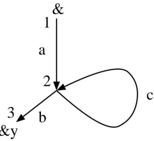
For example, a graphg∈DB{&y} shown in Figure 4 is represented by
({1,2,3},{(1, a,2),(2, c,2),(2, b,3)},{(&,1)},{(3,&y)}).
Edges labeled withϵworks likeϵtransition in automaton in that it identifies source and destination nodes. They are used in establishing connection between nodes. Detailed usages are given in Section 4.3.
3.1.5 UnCAL: A Graph Algebra
&
&y
a
b
c
1
2
3
Figure 4: A simple graph example
and operators, by which arbitrary graphs can be represented. In addition to tree constructors, graph concatenation and cycle operator, together with input and output markers form cycles and confluences by gluing nodes marked with identical markers together.
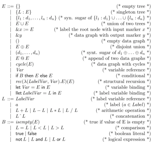
Complete syntax and brief semantics of UnCAL expressions are depicted in Figure 14 in the Appendix.
Contrary to appearance of tree constructor{}and∪, its semantics of unifi-cation is far from those of sets. In UnCAL, although value equality is explicitly defined, duplicate eliminations do not take place. A graph shown in Figure 4 is represented by the following UnCAL expression
&z1@cycle((&z1 := {a:&z2}, &z2 := {c:&z2,b:&z3}, &z3 := &y))
where &z1, &2, &3 correspond to the three nodes respectively, and a, b, c correspond to the three edges.
3.1.6 Extended Graph Bisimulation and Bisimulation Genericness
Graph bisimulation defines value equalities between graph instances. Intuitively, when graphG1andG2are bisimilar, then every nodex1inG1has a counterpart x2 in G2, and if there is an edge formx1 to y1, then there is a corresponding
edge fromx2toy2. UnQL data model extends graph bisimulation by (1)
requir-ing equalities in labels, (2) allowrequir-ing insertion of one or more consecutiveϵedges between normal edge and target node (y1ory2above), (3) requiring
correspon-dence betweenG1.I(&x) and G2.I(&x), (4) requiring correspondence between
output labels of corresponding nodes (output labels may be associated with the node other than corresponding nodes, provided that the label is associated with nodes that can be reached by traversingϵedges).
absorb these divergence, UnQL uses a relation called bisimulation genericness
to establish equivalence class between them: if a function f is bisimulation
generic, then for every component-wise bisimilar pair of n-tuples (g1, . . . , gn)
and (g′
1, . . . , gn′),f(g1, . . . , gn) andf(g1′, . . . , gn′) are bisimilar.
Semantics of UnCAL basic constructors and operators are carefully designed to satisfy bisimulation genericness, so that in tern UnCAL queries as a hole also are bisimulation generic. This allows safe application of various optimization including fusion and tupling.
3.2
UnQL
+UnQL+ is a small extension of UnQL to support convenient specification of
graph transformations (model transformations). we extend UnQL with three editing constructs for transforming graphs. In Section 4.2, we will show that all these editing constructs can be mapped to structural recursions of UnCAL, the core language.
3.2.1 Deleting a Graph
The deletion construct, delete ... where ..., is used to describe deletion
of part of the graph. Consider the class graph in Figure 3, and suppose we want to eliminate all the names of association. This can be described by
delete AssocName where
{association.name: AssocName} in db
where the subgraph matched with AssocName will be deleted from its original graph. In contrast, the following transformation keeps the association names as result.
select {result: AssocName} where
{association.name: AssocName} in db
So, we may consider thedelete as the dual of theselect.
3.2.2 Extending a Graph
The extension construct, extend ... where ..., is used to extend a graph
with another one. For example, we may write the following transformation to
add adateto eachassociation.
extend AG with {date:"2008/8/4"} where
{association: AG} in db
3.2.3 Updating a Graph
The replacement construct,replace ... where ..., is used to replace a
replace G by {tgt:G1} where
{association: G} in db, {dest: G1} in G
3.3
Class2RDBMS in UnQL
+Now we demonstrate, with the example of Class2RDBMS, the usefulness of
UnQL+ in constructing complicated model transformation. The compositional
style allows us to develop bigger model transformations by gluing smaller trans-formations via intermediate models, without worrying about inefficiency due to the intermediate models. This is because unnecessary intermediate models will be removed automatically by our system.
Recall the requirement of the transformation Class2RDBMS in Section 2, where we want to make tables (independent tables or tables pointed by a for-eign key) from a class diagram, where each table should have a name, some a sequence of columns, some of which are pointed by primary or foreign keys. The whole transformation in UnQL+ is given in Figure 6. Let us explain how it is
developed.
It follows directly from the requirement of Class2RDBMS that the top level transformation can be described as follows.
select
{table: {name: {Name: {}}} U MakePKeyCol U MakeGenCol U MakeFKeyCol, table: MakeFKeyTable} where ...
Now to create columns of a table, we need to gather all information of classes that are directly or indirectly associated with the source persistent class. This suggests us to create an intermediate model ChainDB, in which indirectly associated classes are directly associated.
ChainDB in (select
... where
{association:
{name: N1, src: C11, dest: C12}} in db, {association:
{name: N2, src: C21, dest: C22}} in db, {name: {Name12: Any}} in C12,
{name: {Name21: Any}} in C21, Name12 = Name21)
We look for two associations in which one’s destination is the other’s source, and then add a link edge to the indirected destination to the source. The detailed definition ofChainDB is given in Figure 6. Note that we do not need to worry about the relationship between the new and the old models, and this new model is just for intermediate use.
{group: {src:
{name: {Name: Any},
is_persistent: {Persistent: Any}, attrs: As},
chains: Chains}} in ChainDB, Persistent = true,
Note that the symbols starting with a capital character are pattern variables used to save extracted information.
From the information obtained, we can create a primary key for the table
by querying the data from the graphs and add two new edgespkeyandcols.
MakePKeyCol in
(select {pkey: Col, cols: Col} where
{attribute: ...} in As, Primary = true,
Col in {column: ...})
Note that Col is another shared intermediate model (graph), which appears
twice in theselectpart.
We omit explanation of definitions for creating other columns and foreign keys, which are very similar.
As seen from this example, UnQL+enables us to productively develop model
transformations in a compositional manner (we can glue results with unison
operator U or sequentially apply simpler model transformations with some
in-termediate models.) This good result is not surprising, because usefulness of composition has been seen and widely known in development of program trans-formation.
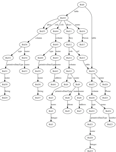
The execution of this model transformation on the class graph in Figure 3 yields the graph in Figure 5, which is essentially the same as the table diagram in Figure 2.
4
Compositional Model Transformation System
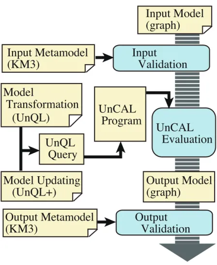
Figure 7 shows an overview of our model transformation system. An input model represented by a graph is validated against a given input metamodel described in Kernel Metametamodel (KM3) [2]. The validated graph is transformed by a
given query described in UnQL and an update described in UnQL+ which will
be introduced later. The transformation is performed by translating them into an UnCAL program, that is a structural recursion over an input graph, after
integrating the UnQL+updating into an UnQL query. The output graph of the
transformation is validated against a give output metamodel in KM3.
4.1
Graph Schema and Validation
Our system validates input and output graphs against given schemata of them. We employ Kernel MetaMetaModel (KM3) to describe schemata because it is
widely used as a metametamodel1 in actual software development and more
1
Bid0 Bid10 table Bid18 table Bid35 pkey cols Bid44 cols Bid11 fkeys Bid16 name Bid27 cols Bid26 name Bid2 Bid1 Integer Bid3 name Bid4 primitiveDataType Bid6 Bid5 phone Bid8 Bid7 address Bid9 name name Bid36 column Bid45 column Bid12 fkey Bid17 Person Bid14 cols Bid13 ref Bid15 column table type name Bid28 column Bid25 Phone Bid20 Bid19 Integer Bid21 name Bid22 primitiveDataType Bid24 Bid23 number type name Bid30 Bid29 String Bid31 name Bid32 primitiveDataType Bid34 Bid33 name type name Bid38 Bid37 String Bid39 name Bid40 primitiveDataType Bid42 Bid41 address Bid43 name type name
select
{table: {name: {Name: {}}} U MakePKeyCol U MakeGenCol U MakeFKeyCol, table: MakeFKeyTable} where
ChainDB in
(select {group: {src:C11,
chains:{dest:{cnames:{name: N1}, class:C12},
dest:{cnames:{name: N1, name:N2}, class:C22}}}, group: {src:C21,
chains:{dest:{cnames:{name:N2}, class:C22}}}}
where {association: {name: N1, src: {class: C11}, dest: {class: C12}}} in db, {association: {name: N2, src: {class: C21}, dest: {class: C22}}} in db, {name: {Name12: Any}} in C12,
{name: {Name21: Any}} in C21, Name12 = Name21),
{group: {src: {name: {Name: Any},
is_persistent: {Persistent: Any}, attrs: As},
chains: Chains}} in ChainDB, Persistent = true,
MakePKeyCol in
(select {pkey: Col, cols: Col}
where {attribute: {name: AName, type: AType, is_primary: {Primary: Any}}} in As, Primary = true,
Col in {column: {name: AName, type: AType}}),
MakeGenCol in
((select {cols: {column: {name: AName, type: AType}}}
where {attribute: {name: AName, type: AType, is_primary: {Primary: Any}}} in As, Primary = "false") U
(select {cols: {column: {name: CNames, type: AType2}}} where {dest:{cnames: CNames,
class:{is_persistent: {Persistent:Any}, attrs:As2}}} in Chains, Persistent = false,
{attribute: {type: AType2}} in As2)),
{dest:{cnames: CNames,
class:{is_persistent: {Persistent:Any}, attrs:As2,
name: Name}}} in Chains, Persistent = true,
{attribute: {type: AType2}} in As2,
MakeFKeyTable in
(select {name: Name, cols: Col}
where {attribute: {name: AName, type: AType, is_primary: {Primary: Any}}} in As2, Col in {column: {name: AName, type: AType}}),
MakeFKeyCol in {fkeys: {fkey: {cols: {name:CNames, type:AType2}, ref: {table: MakeFKeyTable}}}}
Input Model
(graph)
Input Metamodel
(KM3)
Input
Validation
Output
Validation
Output Metamodel
(KM3)
Model
Transformation
(UnQL)
Output Model
(graph)
UnQL
Query
UnCAL
Program
Model Updating
(UnQL+)
UnCAL
Evaluation
Figure 7: Overview of our System
formally defined than other metametamodels. We callKM3 schemafor a
meta-model written in KM3.
A KM3 schema has a structure similar to an XML schema base on regular tree grammar such as W3C XML schema [24] and RELAX NG [6] in the sense that a schema prescribes which kind of set of nodes must be referred to by a node by regular expression. See [2] for details on the specification of KM3.
Figure 8 shows an example of a KM3 schema for classes each of which is an input for the model transformation introduced in Section 2. The schema con-sists of four classes2,Association,Class,AttributeandPrimitiveDataType.
A class has some features, either reference or attribute. Every feature has a type, either class or data type. Since all of them inherit their super class NamedElt, they have an attribute name which is String. The Association class has two referencessrcanddestwhich areClass. TheClassclass has an
2
The term “class” here is used as an jargon of KM3. Do not confuse it with a “class” as an input of the model transformation in Section 2. The latter “class” appears as capitalized
package Class { datatype String; datatype Boolean;
abstract class NamedElt { attribute name : String; }
class Association extends NamedElt { reference src : Class;
reference dest : Class; }
class Class extends NamedElt { attribute is_persistent : Boolean; reference attrs [*] : Attribute; }
class Attribute extends NamedElt { attribute is_primary : Boolean; reference type : PrimitiveDataType; }
class PrimitiveDataType
extends NamedElt { }
}
Figure 8: KM3 Schema for Classes
attribute is persistentwhich isBooleanand arbitrary number of references
attrswhich areAttribute. TheAttributeclass has an attributeis primary
which is Boolean and a reference type which is PrimitiveDataType. The
PrimitiveDataType class has neither attribute nor reference besides an inher-ited attributename.
We validate a graph by matching each edge in them with a name of a class or a feature in a given schema. A validation of a graph proceeds as follows.
1. All class inheritances are eliminated from a given schema by expanding features of classes with their super classes. The elimination is recursively done since a super class may inherit another super class.
2. We associate a vertex following from the root of the graph with a class whose name is the same as the label of the edge between the vertex and the root. For example, vertices Bid28 and Bid34 in Figure 3 are associated with a classAssociation.
This procedure always terminates because the number of vertices are finite. Currently our system does not check the type of UnQL/UnCAL transfor-mation, which is our future work. If it is attained, we do not have to validate either input or output graphs.
4.2
Mapping to the Core Language
UnQL+provides a friendly interface language for users to describe model
trans-formations. For efficient implementation, UnQL+ can be transformed to the
core language UnCAL, where structural recursion plays an important role in supporting efficient composition of model transformations. The mapping from
UnQL+ to UnCAL consists of the following six steps: (1) simplifying where
clauses; (2) removing the editing constructs; (3) transforming simple patterns to structural recursions; (4) transforming regular patterns to mutual structural recursions; (5) tupling mutual structural recursions to single ones; and (6) map-ping structural recursions to those in UnCAL. In the following, we explain these steps one by one.
4.2.1 Simplifying Where Clauses
In the second step, (Step2) in Figure 9 transforms an UnQL query into one
with only single patterns by applying (Rule1) to (Rule5) according to the
patterns of BindCond in the where expression. Theses rules in Figure 9 are
applied recursively based on the inductive definition of UnQL. Inference rules for a judgement of the formt−−−−→apstp2 t′ are shown in Figure 15 in Appendix.
(Rule1) and (Rule3) are from the original paper. (Rule2) is to represent
a compositional expression. (Rule4) and (Rule5) are to lift a constant leaf node up to an edge because in UnCAL data model all information is stored as labels on edges and, bothnewv andanyv are fresh variable names.
For example, onQ1described in Section 3 these rules produce:
(* Q1’ *) select T
where {association:V1} in db, {dest:V2} in V1, {class:V3} in V2, {attrs:V4} in V3, {attribute:V5} in V4, {type:V6} in V5,
{primitiveDataType.name:T} in V6
In this query, the pattern
{association:{dest:{class:{attrs:{attribute: {type:{primitiveDataType.name:T}}}}}}}
in the BindCond in Q1 is split into single patterns using fresh variable names
V1. . .V6.
4.2.2 Eliminating Editing Constructs
v::Var {pei:pati}inv::BindCond pat
−−→bsi::BindCondlist (i= 1, . . . , n)
{pe1:pat1, . . . ,pen:patn}inv::BindCond pat
−−→bs1++· · ·++bsn::BindCondlist
(Rule1)
newv::Var t::Template−−−−→apstp2 t′::Template
{pei:pati}innewv::BindCond−−→pat bsi::BindCondlist (i= 1, . . . , n)
{pe1:pat1, . . . ,pen:patn}int::BindCond pat
−−→newvint′,(bs1++· · ·++bsn)::BindCondlist (Rule2)
pat::{PE1:Pat1, . . . ,PEn:Patn} t::Template apstp2
−−−−→t′::Template newv ::Var patinnewv ::BindCond−−→pat bs ::BindCondlist
{pe:pat}int::BindCond−−→ {pat pe:newv}int′,bs::BindCondlist (Rule3)
c::Const t::Template−−−−→apstp2 t′::Template
{pe:c}int::BindCond−−→ {pat pe:newv}int′,{c:anyv}innewv::BindCondlist (Rule4)
c::Const t::Template−−−−→apstp2 t′::Template
cint::BindCond−−→pat [{c:{}}int′]::BindCondlist
(Rule5)
t::Template−−−−→apstp2 t′::Template bc1::BC−→bc bs1::BClist · · · bc n::BC
bc
−→bsn::BClist
select t where bc1, . . . ,bcn::Query step2
−−−→select t′ where bs1++· · ·++bsn::Query
(Step2)
bc::BindCond−−→pat bs::BindCondlist
bc<:BC−→bc bs<:BClist
bc::BoolCond
bc<:BC −→bc [bc]<:BClist
First, deletion or extension of a subgraph can be expressed by thereplace construct based on the following two rules.
delete G where ... => replace G by {} where ...
extend G with G1 where ... => replace G by G U G1 where ...
Second, thereplaceconstruct can be eliminated using theselectconstruct and structural recursions. After simplification of the where clause, the where
clause becomes a sequence of boolean conditions bc of relation expressions r
such as A=5, simple pattern-in boolean expressions pi such as {P:G1} in G2,
or simple binding expressions bd such as G in template. So the form to be
transformed is
replaceG1 byG2 wherebc1, . . . , bck−1,{pe:G1}, bck+1, . . . , bcn
where bc1, . . . , bck−1 are either relation expressions or pattern-in boolean
ex-pressions. Our transformation rules are as follows.
replace G1 by G2 where {l:{}} in D, r1,...,rm, rest =>
let sfun h1{L:G} =
if L=l and isEmpty(G) and r1 and ... and rm then replace G1 by G2 where rest
else {L:G} in h1(D}
replace G1 by G2 where {L:{}} in D, r1,...,rm, rest =>
let sfun h1{L:G} =
if isEmpty(G) and r1 and ... and rm then replace G1 by G2 where rest
else {L:G} in h1(D}
replace G1 by G2 where {l:G3} in D, r1,...,rm, rest => { condition: G1 /= G3 }
let sfun h1{L:G3} =
if L=l and r1 and ... and rm then {L:(replace G1 by G2 where rest)} else
{L:G3} in h1(D}
replace G1 by G2 where {L:G3} in D, r1,...,rm, rest => { condition: G1 /= G3 }
let sfun h1{L:G3} =
if r1 and ... and rm then
{L:(replace G1 by G2 where rest)} else
{L:G3} in h1(D}
=> { condition: G1 = G3 } let sfun h1{L:G3} =
if L=l and r1 and ... and rm then
letval G1’ = select {l:{}} where rest in letval G2’ = select G2 where rest in if isEmpty(G1’) then {L:G3} else {L:G2’} else
{L:G3} in h1(D}
replace G1 by G2 where {L:G3} in D, r1,...,rm, rest => { condition: G1 = G3 }
let sfun h1{L:G3} =
if r1 and ... and rm then
letval G1’ = select {l:{}} where rest in letval G2’ = select G2 where rest in if isEmpty(G1’) then {L:G3} else {L:G2’} else
{L:G3} in h1(D}
replace {L:G1} by G2 where {L:G3} in D, r1,...,rm, rest => { condition: G1 = G3 }
let sfun h1{L:G3} =
if r1 and ... and rm then
letval G1’ = select {l:{}} where rest in letval G2’ = select G2 where rest in if isEmpty(G1’) then {L:G3} else {G2’} else
{L:G3} in h1(D}
As an example, consider the following expression.
replace Name by Name’ where
{association:Assoc} in db, {name:Name} in Assoc, {string:Na} in Name, {N:{}} in Na,
N = "phone",
Name’ in {string:{"assoc"^N":{}}}
It can be desugared to the following.
let sfun h1{L:Assoc} = if L=association then
let sfun h2 {L:Name} = if L=name then
letval G1’ = (select {name:{}} where
{string:Na} in Name, {N:{}} in Na,
Name’ in {string:{"assoc"^N":{}}}) in letval G2’ = (select G2
where
{string:Na} in Name, {N:{}} in Na,
N = "phone",
Name’ in {string:{"assoc"^N":{}}}) in if isEmpty{G1’) then {L:Name} else {L:G2’}
else {L:Name} in h2(Assoc) else {L:Assoc} in h1(db)
4.2.3 From Patterns to Structural Recursions
In the third step, we apply (Step3) in Figure 10. (Step3) transforms an UnQL, generated by the second step, into structural recursion with letval and filter
expressions. In Figure 10, (RuleA) and (RuleD) are from the original paper.
(RuleB) is used to represent binding values to variables by letval expressions
newly introduced by us. (RuleC) is to represent Boolean conditions in where expressions by newly introduced filter expressions. Note that like the original paper,restused in (RuleA),(RuleB) and (RuleC) is a syntactic meta-variable which stands for the remaining clauses in thewherecomponent. Theses rules in Figure 10 are also applied recursively based on the inductive definition of UnQL. Inference rules for a judgement of the formt−−−−→apstp3 t′ are shown in Figure 16 in Appendix.
When applied toQ1’, the result is:
let sfun h1({association:V1}) = let sfun h2({dest:V2}) =
let sfun h3({class:V3}) = let sfun h4({attrs:V4}) =
let sfun h5({attribute:V5}) = let sfun h6({type:V6}) =
let sfun h7({primitiveDataType.name:T}) = T
in h7(V6) in h6(V5) in h5(V4) in h4(V3) in h3(V2) in h2(V1) in h1(db)
4.2.4 Regular Path Patterns
selectewhererest::Query−→sr t::Template e′::Template−−−−→apstp3 t′::Template selectewhere({pe:pat}ine′,rest)::Query−→sr let sfunh({pe:pat}) =tinh(t′)::Template
(RuleA)
v::Var selectewhererest::Query−→sr t::Template e′::Template−−−−→apstp3 t′::Template
selectewhere(vine′,rest)::Query−→sr letvalv:=t′int::Template (RuleB)
v::Var selectewhererest::Query−→sr t::Template
selectewhere(bc,rest)::Query−→sr filter(bc, t)::Template (RuleC)
selectewhere()::Query−→sr e::Template (RuleD)
e::Template−−−−→apstp3 t::Template selecttwherebs::Query−→sr t′::Template
selectewherebs::Query−−−→step3 t′::Template
(Step3)
Figure 10: Third step: Patterns are transformed into structural recursion.
Automaton) and associating a function with each state. This transformation is achieved by the standard way in transformation from regular expressions to NFA without epsilon. The generated functions are mutually recursive. Note that unlike the original paper, function application associated with terminal states is unioned with not the argument of the function but an identity function application with the argument. This transformation enables us to apply the optimization technique, called fusion, described in Section 4.4.
For example, consider the regular expression_*.primitiveDataType.name
in Q2, an equivalent non-deterministic automaton3 has five states and the
fol-lowing transitions : s1
Any −−−→s4, s1
Any −−−→s5, s1
primitiveDataT ype −−−−−−−−−−−−−→s3,
s3
name −−−−→s2, s4
primitiveDataT ype −−−−−−−−−−−−−→s3,
s5
Any −−−→s4, s5
Any −−−→s5, s4
primitiveDataT ype −−−−−−−−−−−−−→s3
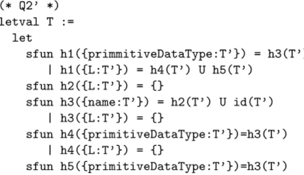
The initial state iss1 and the terminal state is s2. So,Q2 is equivalent to
the following mutual structural recursion,Q2’.
(* Q2’ *) letval T :=
let
sfun h1({primmitiveDataType:T’}) = h3(T’) | h1({L:T’}) = h4(T’) U h5(T’)
sfun h2({L:T’}) = {}
sfun h3({name:T’}) = h2(T’) U id(T’) | h3({L:T’}) = {}
sfun h4({primitiveDataType:T’})=h3(T’) | h4({L:T’}) = {}
sfun h5({primitiveDataType:T’})=h3(T’)
3
| h5({L:T’}) = h4(T’) U h5(T’) sfun id({L:T’}) = {L:id(T’)} in h1(db)
in T
In this query, each function corresponds to a state, and has one pattern for each symbol occurring on some transition from that sate. Since s2 is the
terminal state, h2(T’)occurs in the right hand side with unioned withid(T’), whereid()is an identity function.
4.2.5 Tupling Mutual Structural Recursions
In the fifth step, tupling is applied to mutually recursive functions. Tupling [15] is a standard way to transform mutual recursive functions into a single one by defining a new function that returns a tuple of results each corresponding to a function that is mutually defined with others. The tupling transformation of mutual structural recursions has been given in [5], so we omit the details but just give an example.
By applying the tupling to the mutually recursionQ2’, we can have the fol-lowing single recursive functionh1h2h3h4h5id(). Note that this is an illustrative expression, so the following expression has a mixture of UnQL and UnCAL syntax.
letval T := let
sfun h1h2h3h4h5id(name:T’) = (&z1 := &z4 U &z5,
&z2 := {},
&z3 := &z2 U &z6, &z4 := {},
&z5 := &z4 U &z5, &z6 := {name:&z6}) | h1h2h3h4h5id(primitiveDataType:T’) =
(&z1 := &z3, &z2 := {},
&z3 := {}, &z4 := &z3,
&z5 := &z3,
&z6 := {primitiveDataType:&z6}) | h1h2h3h4h5id(L:T’) =
(&z1 := &z4 U &z5, &z2 := {},
&z3 := {}, &z4 := {},
&z5 := &z4 U &z5, &z6 := {L:&z6}) in &z1@h1h2h3h4h5id(db)
in T
4.2.6 Mapping to UnCAL
4.3
Interpretation of the Core Language
4.3.1 Interpreting Structural Recursion
UnQL paper [5] provides two evaluation strategies that are proved to be equiv-alent: bulk semantics and recursive semantics. The latter is intuitive in that applications of body expression (e1 in rec(e1)(e2)) take place in a top-down
fashion. Revisiting of nodes caused by cycles can be correctly handled by mem-oization. The former deals possible cycles by applyinge1 once for every edge in
input graph and connect together using Skolem functions on markers and nodes. We describe here two peculiar aspects of our implementation in bulk semantics. Implementation of recursive semantics was fairly straightforward.
Skolem Functions In bulk semantics, graph is represented by independent set comprehensions on nodes, edges and markers. “Rendezvous” between them is required through Skolem functions: you have to glue nodes whose Skolem
function values are identical. We implemented the function using a set of
OCaml’s constructor of algebraic data structure (variants) which directly re-flects recursive nature of Skolem function (result of application of the function to node ID is again a node ID), so that there is a one-to-one mapping between Skolem function and constructor. It also allowed us almost straight-forward implementation of set comprehensions using standard Set library and fold op-erations on the Set instances.
Caching Values of the Body Expression Since we use identities of nodes encoded with instances of the algebraic data structures, and create fresh iden-tities for each evaluation of tree constructors, each evaluation on e1 produces
“different” instances for identical inputs. Therefore, values of e1 are obtained
collectively beforehand and stored into tables. Looking up the cache value of the value of e1 instead of evaluating in the set comprehensions allows correct
rendezvous between nodes and edges, as well as elimination of recomputation.
4.3.2 Epsilon Edge Elimination
Bulk semantics generously introduces epsilon edges. They are eliminated when necessary using straightforward algorithm.
Static Type Estimation Regardless of evaluation strategy, rec requires static estimation of input and output markers ofe1. In UnCAL, this information
is called type. Inference rules of the estimation, which may be non-trivial, is depicted in Figure 11.
Dynamic Semantics of UnCAL Figure 17 in Appendix shows concrete
dynamic semantics of major UnCAL expressions exceptrec, which are already
explained.
4.4
Model Compositions
d∈DBXY Y ⊆ Y′
d∈DBXY′
{} ∈DBY
d∈DBY
{l:d} ∈DBY
d1, d2∈DBY
d1∪d2∈DBY
d1, d2∈DBXY
d1∪d2∈DBXY
()∈DB∅Y d∈DBY
&x:=d∈DB{Y&x}
d∈DBZY
&x·d∈DB{Y&x}·Z
y∈ Y &y∈DBY
d1∈DBXY1 d2∈DBXY2 X1∩ X2=∅ d1⊕d2∈DBXY1∪X2
d1∈DBXY d2∈DBYZ d1@d2∈DBXZ
d1∈DBXX ∪Y cycle(d)∈DBXY
e:Label×DBY → DBZZ d∈DBXY
rec(e)(d)∈DBX ·ZY·Z
et∈DBXY ef ∈DBXY
ifb then et else ef ∈DBXY
Figure 11: UnCAL Typing Rules
T2: M′= (T2◦T1)(M) =T2(T1(M)). Second one is a pair of transformations T1 and T2, that share identical input model: (M1,M2) = (T1△T2)(M)
def
= (T1(M), T2(M))). In the first composition, intermediate result can be
elimi-nated by fusion technique, while in the second composition, duplicate traversal of the input model can be unified by tupling technique. Since tupling at this level is not implemented, only fusion is described in this section.
4.4.1 Fusing Model Composition
In our framework, consecutive model transformations are translated into com-positional UnQL queries. Since these queries are translated into composition of structural recursions in UnCAL, fusion transformation for UnCAL that is pro-posed in [5] is directly applicable. For very simple case, consider the following scenario4: first apply Q3to model in Figure 3, and then retrieve all names by
the following query Q4. (* Q4 *)
select
letrec sfun f2 ({name:T}) = {name:g2(T)} | f2 ({L:T}) = f2(T)
and sfun g2 ({L:T}) = {L:g2(T)} in f2(db))
Note that since these transformations are for illustrative purpose, KM3 val-idation to intermediate and final result may fail.
Compositional query would look like the following queryQ5, by which our
desugaring module produces an UnCAL queryQ6. Our UnCAL rewriter
trans-late it into Q7, which is equivalent toQ8, which is further simplified by hand. Tworecs in Q6is fused into one rec inQ7.
Table 1 shows execution times ofQ5for each evaluation strategy ofrec. The experiment was conducted on a 1.5GHz quad Xeon SMP machine running Linux kernel 2.4.20. About 3 to 5 fold speed-up had been confirmed.
(* Q5 *)
4
evaluation strategy ofrec
before fusion
after fusion
speedup ratio
bulk 1.31 0.25 5.32
recursive 2.08 0.73 2.86
Table 1: Execution time [sec] ofQ5
select
letrec sfun f2 ({name:T}) = {name:g2(T)} | f2 ({L:T}) = f2(T) and sfun g2 ({L:T}) = {L:g2(T)} in
letrec sfun f1 ({primitiveDataType:T}) = {primitiveDataType:g1(T)} | f1 ({L:T}) = {L:f1(T)} and sfun g1 ({name:T})= {typeName:g1(T)}
| g1 ({L:T}) = {L:g1(T)} in f2(f1(db))
(* Q6 *) &z1@rec(\ (L,T).
if L = "name"
then (&z1 := {"name": &z2}, &z2 := {"name": &z2})
else (&z1 := &z1, &z2 := {L: &z2})) (&z1@rec(\ (L,T).
if L = "name"
then (&z1 := {"name": &z1}, &z2 := {"typeName": &z2}) else if L = "primitiveDataType"
then (&z1 := {"primitiveDataType": &z2}, &z2 := {"primitiveDataType": &z2}) else (&z1 := {L: &z1}, &z2 := {L: &z2})) (db))
(* Q7 *)
&z1@(&z2 := &z1&z2, &z1 := &z1&z1)@ rec(\ (Sa1,T).
if Sa1="name"
then (&z1 := (&z1 := {"name": &z2}, &z2 := {"name": &z2}) @ (&z2 := &z1&z2, &z1 := &z1&z1),
&z2 := (&z1 := &z1,
&z2 := {"typeName": &z2}) @ (&z2 := &z2&z2, &z1 := &z2&z1)) else if Sa1 = "primitiveDataType"
then (&z1 := (&z1 := &z1,
&z2 := {"primitiveDataType": &z2}) @ (&z2 := &z2&z2, &z1 := &z2&z1),
&z2 := (&z1 := &z1,
&z2 := {"primitiveDataType": &z2}) @ (&z2 := &z2&z2, &z1 := &z2&z1))
if L = "name"
then (&z1 := {"name": &z2}, &z2 := {"name": &z2}) else (&z1 := &z1, &z2 := {L: &z2})
@ (&z2 := &z1&z2, &z1 := &z1&z1), &z2 := llet L = Sa1 in if L = "name"
then (&z1 := {"name": &z2}, &z2 := {"name": &z2}) else (&z1 := &z1, &z2 := {L: &z2})
@ (&z2 := &z2&z2, &z1 := &z2&z1)))(db)
(* Q8 *)
&z1@(&z2 := &z1&z2, &z1 := &z1&z1)@ rec(\ (Sa1,T).
if Sa1="name"
then (&z1&z1 := {"name": &z1&z2}, &z1&z2 := {"name": &z1&z2}, &z2&z1 := &z2&z1,
&z2&z2 := {"typeName": &z2&z2}) else if Sa1 = "primitiveDataType"
then (&z1&z1 := &z2&z1,
&z1&z2 := {"primitiveDataType": &z2&z2}, &z2&z1 := &z2&z1,
&z2&z2 := {"primitiveDataType": &z2&z2} else (&z1 := llet L = Sa1 in
if L = "name"
then (&z1 := {"name": &z1&z2}, &z2 := {"name": &z1&z2}) else (&z1 := &z1&z1,
&z2 := {L: &z1&z2}), &z2 := llet L = Sa1 in
if L = "name"
then (&z1 := {"name": &z2&z2}, &z2 := {"name": &z2&z2}) else (&z1 := &z2&z1,
&z2 := {L: &z2&z2}) ))(db)
The following two rules are main transformation rules for cascadingrec’s. The first rule is applied when e2(l, t) does not depend ont. Second rule is
ap-plied otherwise.
rec(e2)◦rec(e1) =rec(rec(e2))◦e1 rec(e2)◦rec(e1) =
rec(λ(l, t).rec(e2)(e1(l, t) @rec(e1)(t)))
Following rules are also used to make recursive application of the above fusion rules to subexpressions possible.
rec(e)({}) = {}
rec(e)({l:d}) = e(l, d) @rec(e)(d)
rec(e)(d1∪d2) = rec(e)(d1)∪rec(e)(d2) rec(e)(&x:=d) = &x·(rec(e)(d))
Z={&z1, . . . ,&zp} e∈DBZZ
&x:= (&z:=e)↓&x.&z:=e &x:= (e1⊕e2)↓(&x:=e1)⊕(&x:=e2)
e∪ {} ↓e {} ∪e↓e
e⊕()↓e ()⊕e↓e
() @e↓()
cycle(())↓() cycle({})↓ {} e∈DB
X
Y X ∩ Y =φ
cycle(e)↓e
Figure 12: Auxiliary rewriting rules
rec(e)() = ()
rec(e)(d1⊕d2) = rec(e)(d1)⊕rec(e)(d2)
tdoes not occur free ine
rec(λ(l, t).e)(d1@d2) =rec(e)(d1) @rec(e)(d2) tdoes not occur free ine
rec(λ(l, t).e)(cycle(d)) =cycle(rec(e)(d))
Figure 12 shows additional rules to further simplify the body ofrec. There may be other rules applicable. Exploring these rules s a part of our future works.
5
Related Work
Our work is very much related to research on model transformation based on graph transformation in the software engineering community, as well as on re-search on graph querying in the database community.
In the software engineering community, graph transformation has been widely used for expressing model transformations [10, 19, 16].
AGG [23, 9] is a well-known rule-based visual tool which supports an al-gebraic approach to graph transformation. AGG supports typed (attributed) graph transformations including type inheritance and multiplicities. Rule appli-cation can contain non-deterministic choice of rules which may be controlled by rule layers. Different from our approach, AGG does not have a clear separation between the source and target graphs, it is not straightforward to compose/write multi-staged transformations in AGG.
Neither AGG nor TGG has strict control over application of elementary al-gebraic graph transformation rules. To increase usability and efficiency of graph transformation, a variety of control concepts for rule and match selection have been considered in many graph transformation approaches such as VIATRA [4] and VMTS [18], where graph transformations are controlled with recursive graph patterns. Unlike AGG and TGG, graph transformation rules are guar-anteed to be executable, which is a main conceptual difference. Since their recursive control structures can be very complicated, it remains unclear how to efficiently compose them. Our approach puts reasonable restriction on the recursive structure so that it cannot only be powerful enough to specify various model transformations but also suitable for efficient composition.
On the other hand, in the database community, there have been a lot of work on language design and implementation for efficient graph querying [13, 22, 5]. Different from querying trees, issues on representation and equivalence of graphs are subtle and important to define correctness of graph querying (as well as graph transformation), and the use of bisimulation and structural recursion in [5] leads to a very nice framework for both declarative and efficient graph querying with high modularity and composability. This has motivated us to see if we can extend the framework from graph querying to graph transformation.
6
Conclusion
In this paper, we have reported our first attempt to designing and implementing a compositional framework for model transformations based on UnQL. Although UnQL is well known in database community for its unique solution to the com-position problem, no one, as far as we are aware, has recognized its usefulness in software development. We have shown that it is indeed useful and the main theory and technique can be applied to solve the composition problem in model transformations.
We are currently working on extending this framework further to add “bidi-rectionality” to the compositional model transformation so that updating the target model can be reflected in the source model. This would combine the in-teresting idea on bidirectional computation in both programming language and software engineering communities.
Acknowledgements
We would like to thank Mary Fernandez from AT&T Labs Research, who kindly provided us with the SML source codes of an UnQL system, which helped us a lot in implementing our extended system in OCaml.
References
[1] Zena M. Ariola and Jan Willem Klop. Equational term graph rewriting.
In 704, page 55. Centrum voor Wiskunde en Informatica (CWI), ISSN
0169-118X, 30 1995.
[2] ATLAS group. KM3:Kernel MetaMetaModel manual.
http://www.eclipse.org/gmt/atl/doc/.
[3] J. Bezivin, B. Rumpe, and Tratt L Sch¨urr A. Model transformation in
practice workshop announcement. InMTiP 2005, International Workshop
on Model Transformations in Practice (Satellite Event of MoDELS 2005).
Springer-Verlag, 2005. http://sosym.dcs.kcl.ac.uk/events/mtip/.
[4] Egon B¨orger, Angelo Gargantini, and Elvinia Riccobene, editors.
Ab-stract State Machines, Advances in Theory and Practice, 10th International
Workshop, ASM 2003, Taormina, Italy, March 3-7, 2003, Proceedings,
vol-ume 2589 ofLecture Notes in Computer Science. Springer, 2003.
[5] Peter Buneman, Mary F. Fernandez, and Dan Suciu. UnQL: a query lan-guage and algebra for semistructured data based on structural recursion.
VLDB Journal: Very Large Data Bases, 9(1):76–110, 2000.
[6] James Clark and Makoto Murata. RELAX NG specification.
http://www.oasis-open.org/committees/relax-ng/spec.html, 2001.
[7] Andrea Corradini and Fabio Gadducci. A 2-categorical presentation of term
graph rewriting. InCategory Theory and Computer Science, pages 87–105,
1997.
[8] Krzysztof Czarnecki and Simon Helsen. Classification of model
transfor-mation approaches. InWorkshop on Generative Techniques in the Context
of Model-Driven Architecture, 2003.
[9] Hartmut Ehrig, Karsten Ehrig, Gabriele Taentzer, Juan de Lara, D´aniel
Varr´o, and Szilvia Varr´o-Gyapay. Termination criteria for model
trans-formation. In James R. Cordy, Ralf L¨ammel, and Andreas
Win-ter, editors, Transformation Techniques in Software Engineering, volume
05161 of Dagstuhl Seminar Proceedings. Internationales Begegnungs- und
Forschungszentrum f¨ur Informatik (IBFI), Schloss Dagstuhl, Germany,
2005.
[10] Karsten Ehrig, Esther Guerra, Juan de Lara, Laszl´o Lengyel, Tiham´er
Levendovszky, Ulrike Prange, Gabriele Taentzer, D´aniel Varr´o, and Szilvia Varr´o-Gyapay. Model transformation by graph transformation: A
compar-ative study. In MTiP 2005, International Workshop on Model
Transfor-mations in Practice (Satellite Event of MoDELS 2005). Springer-Verlag,
2005.
[11] D. S. Frankel. Model Driven Architecture: Applying MDA to Enterprise
[12] Holger Giese and Robert Wagner. Incremental model synchronization with triple graph grammars. In Oscar Nierstrasz, John Whittle, David Harel,
and Gianna Reggio, editors, Models ’06: Proc. of the 9th International
Conference on Model Driven Engineering Languages and Systems, volume
4199 ofLecture Notes in Computer Science, pages 543–557. Springer Verlag, October 2006.
[13] R. Giugno and D. Shasha. Graphgrep: A fast and universal method for querying graphs, 2002.
[14] Lars Grunske, Leif Geiger, and Michael Lawley. A graphical specification of model transformations with triple graph grammars, 2005.
[15] Zhenjiang Hu, Hideya Iwasaki, Masato Takeichi, and Akihiko Takano.
Tu-pling calculation eliminates multiple data traversals. In ACM SIGPLAN
International Conference on Functional Programming (ICFP’97), pages
164–175, Amsterdam, The Netherlands, June 1997. ACM Press.
[16] Frederic Jouault and Ivan Kurtev. Transforming models with ATL. In
Proceedings of Satellite Events at the MoDELS 2005 Conference, volume
3844 ofLecture Notes in Computer Science, pages 128–138. Springer, 2006.
[17] Alexander Konigs and Andy Schurr. Tool integration with triple graph
grammars - a survey. Electronic Notes in Theoretical Computer Science,
148(1):113–150, February 2006.
[18] L´aszl´o Lengyel, Tiham´er Levendovszky, Gerely Mezei, and Hassan Charaf.
Model transformation with a visual control flow language. International
Journal of Computer Science (IJCS), 1(1):45–53, 2006.
[19] OMG. MOF QVT final adopted specification.
http://www.omg.org/docs/ptc/05-11-01.pdf, 2005.
[20] Terrence W. Pratt. Pair grammars, graph languages and string-to-graph translations. J. Comput. Syst. Sci., 5(6):560–595, 1971.
[21] Grzegorz Rozenberg, editor.Handbook of Graph Grammars and Computing
by Graph Transformations, Volume 1: Foundations. World Scientific, 1997.
[22] Lei Sheng, Z. Meral Ozsoyoglu, and Gultekin Ozsoyoglu. A graph query language and its query processing. InICDE, pages 572–581, 1999.
[23] Gabriele Taentzer. AGG: A graph transformation environment for model-ing and validation of software. In John L. Pfaltz, Manfred Nagl, and Boris
B¨ohlen, editors,AGTIVE, volume 3062 ofLecture Notes in Computer
Sci-ence, pages 446–453. Springer, 2003.
Query ::= selectTemplate whereBC1, . . . ,BCn
Template ::= {TE1:Template1, . . . ,TEn:Templaten}
| Var
| (Query)
| Template1∪Template2
| FName(Template)
| let sfunFName1({PE11:Pat11}) =Template11
| FName1({PE12:Pat12}) =Template12
, . . . ,
| FName1({PE1m
1 :Pat1m
1}) =Template1m1
sfunFNamen({PEnmn:Patnmn}) =Templatenmn
in Template
| (Template1, . . . ,Templaten)
| filter(BoolCond,Template)
| letvalVar:=Template1inTemplate2
TE ::= ValExp ValExp ::= Var
| Const
| notValExp
| isEmptyValExp
| ValExp1andValExp2
| ValExp1orValExp2
| ValExp1 =ValExp2
| ValExp1 <ValExp2
| ValExp1 >ValExp2
BC ::= BindCond
| BoolCond BindCond ::= PatinTemplate
BoolCond ::= ValExp
Pat ::= {PE1:Pat1, . . . ,PEn:Patn}
| Var
| Const PE ::= Var
| Const
| RPP
RPP ::= Label
|
| (RPP.RPP)
| (RPP|RPP)
| RPP?
| RPP∗
Const ::= Bool
| String
| Int
E
::=
{}
(* empty tree *)
| {
L
:
E
}
(* singleton tree *)
| {
l
1:
d
1, . . . , l
n:
d
n}
(* syn. sugar of
{
l
1:
d
1} ∪
. . .
∪ {
l
n:
d
n}
*)
|
E
∪
E
(* union of two trees *)
|
&
x
:=
E
(* label the root node with input marker
x
*)
|
&
y
(* data graph with output marker
y
*)
|
()
(* empty data graph *)
|
E
⊕
E
(* disjoint union *)
|
(
d
1, . . . , d
n)
(* synt. sugar of
d
1⊕
. . .
⊕
d
n*)
|
E
@
E
(* append of two data graphs *)
|
cycle
(
E
)
(* data graph with cycles *)
|
Var
(* variable reference *)
|
if
B
then
E
else
E
(* conditional *)
|
rec
(
λ
(
LabelVar
,
Var
)
.E
)(
E
)
(* structural recursion *)
|
let
Var
=
E
in
E
(* variable binding *)
|
llet
LabelVar
=
L
in
E
(* label variable binding *)
L
::=
LabelVar
(* label variable reference *)
|
a
(* label (
a
∈
Label
) *)
|
L
+
L
|
L
−
L
|
L
∗
L
|
L / L
(* arithmetic operation *)
|
L
ˆ
L
(* concatenation *)
B
::=
isempty
(
E
)
(* true if value of E is empty *)
|
L
=
L
|
L < L
|
L > L
(* comparison *)
|
true
|
false
(* boolean literal *)
|
not
L
|
L
and
L
|
L
or
L
(* logical expression *)
t1::Template
apstp2 −−−−→t′
1::Template . . . tn::Template apstp2 −−−−→t′
n::Template {te1:t1, . . . ,ten:tn}::Template
apstp2 −−−−→ {te1:t′
1, . . . ,ten:t′n}::Template
v::Var
v <:Template−−−−→apstp2 v <:Template
q::Query−−−→step2 q′::Query
q <:Template−−−−→apstp2 q′<:Template
t1::Template
apstp2
−−−−→t′1::Template t
2::Template
apstp2 −−−−→t′
2::Template t1∪t2::Template
apstp2 −−−−→t′
1∪t′2::Template
t::Template−−−−→apstp2 t′::Template
f(t)::Template−−−−→apstp2 f(t′)::Template
t1::Template
apstp2 −−−−→t′
1::Template . . . tn::Template apstp2 −−−−→t′
n::Template t::Template apstp2
−−−−→t′::Template
let sfunf1({pe1:pat1}) =t1, . . . ,sfunfn({pen:patn}) =tnint::Template apstp2 −−−−→ let sfunf1({pe1:pat1}) =t′1, . . . ,sfunfn({pen:patn}) =t′nint′::Template
t1::Template−−−−→apstp2 t′
1::Template tn::Template apstp2 −−−−→t′
n::Template
(t1, . . . , tn)::Template apstp2 −−−−→(t′
1, . . . , t′n)::Template
t::Template−−−−→apstp2 t′::Template
filter(bc, t)::Template−−−−→apstp2 filter(bc, t′)::Template
t1::Template
apstp2
−−−−→t′1::Template t
2::Template
apstp2 −−−−→t′
2::Template letvalv:=t1int2::Template
apstp2
−−−−→letvalv:=t′
1int′2::Template
v::Var
v <:Template−−−−→apstp3 v <:Template
q::Query−−−→step3 q′::Query
q <:Template−−−−→apstp3 q′<:Template
t1::Template
apstp3
−−−−→t′1::Template t
2::Template
apstp3 −−−−→t′
2::Template t1∪t2::Template
apstp3 −−−−→t′
1∪t′2::Template
t::Template−−−−→apstp3 t′::Template
f(t)::Template−−−−→apstp3 f(t′)::Template
t1::Template
apstp3 −−−−→t′
1::Template . . . tn::Template apstp3 −−−−→t′
n::Template t::Template apstp3
−−−−→t′::Template
let sfunf1({pe1:pat1}) =t1, . . . ,sfunfn({pen:patn}) =tnint::Template apstp3 −−−−→ let sfunf1({pe1:pat1}) =t′1, . . . ,sfunfn({pen:patn}) =t′nint′::Template
t1::Template−−−−→apstp3 t′
1::Template tn::Template apstp3 −−−−→t′
n::Template
(t1, . . . , tn)::Template apstp3 −−−−→(t′
1, . . . , t′n)::Template
t::Template−−−−→apstp3 t′::Template
filter(bc, t)::Template−−−−→apstp3 filter(bc, t′)::Template
t1::Template
apstp3
−−−−→t′1::Template t
2::Template
apstp3 −−−−→t′
2::Template letvalv:=t1int2::Template
apstp3
−−−−→letvalv:=t′
1int′2::Template
i(g)def= {&x|(&x, v)∈g.I} o(g)def= {&y|(v,&y)∈g.I}
v∈Vˆ
{} ⇒({v}, φ,{(&, v)}, φ)
e⇒g v /∈g.V g.I(&) =r p→l
{p:e} ⇒(g.V ∪ {v}, g.E∪ {(v, l, r)}, g.I\(&, r)∪ {(&, v)}, g.O)
v∈Vˆ
&x⇒({v}, φ,{(&, v)},{(v,&x)})
e⇒g
&x:=e⇒(g.V, g.E,{(&x.&m, v)|(&m, v)∈g.I}, g.O)
e1⇒g1 e2⇒g2 X1=i(g1)X2=i(g2)X1=X2 E1={(v, ϵ, g1.I(&x))|&x∈ X1, v∈V , v /ˆ ∈g1.V, v /∈g2.V} E2={(v, ϵ, g2.I(&x))|&x∈ X1,(v, a, u)∈E1, g1.I(&x) =v}
V ={u|(u, e, v)∈E1}
I={(&x, u)|(u, a, v)∈E1,&x∈ X1, g1.I(&x) =v} e1∪e2⇒(g1.V ∪v2.V ∪V, g1.E∪g2.E∪E1∪E2, I, g1.O∪g2.O)
()⇒(φ, φ, φ, φ) e1⇒g1 e2⇒g2 X1=i(g1)X2=i(g2)X1∩ X2=φ
e1⊕e2⇒(g1.V ∪g2.V, g1.E∪g2.E, g1.I∪g2.I, g1.O∪g2.O)
e1⇒g1e2⇒g2
E={(u, ϵ, v)|(u,&y)∈g1.O,(&x, v)∈g2.I,&y= &x} e1@e2⇒(g1.V ∪g2.V ∪V, g1.E∪g2.E∪E, g1.I, g2.O)
e⇒g X =i(g)Y=o(g)Z=X ∩ Y
I={(&x, u)|(&x, u)∈g.I,&x∈ Z}
O={(v,&y)|(v,&y)∈g.O,&y∈ Z}
E={(u, ϵ, v)|(u,&y)∈O,(&x, v)∈I,&y= &x}
cycle(e)⇒(g.V, g.E∪E, g.I\I, g.O\O)

![Table 1: Execution time [sec] of Q5](https://thumb-ap.123doks.com/thumbv2/123deta/8631509.449612/27.892.308.581.187.274/table-execution-time-sec-of-q.webp)